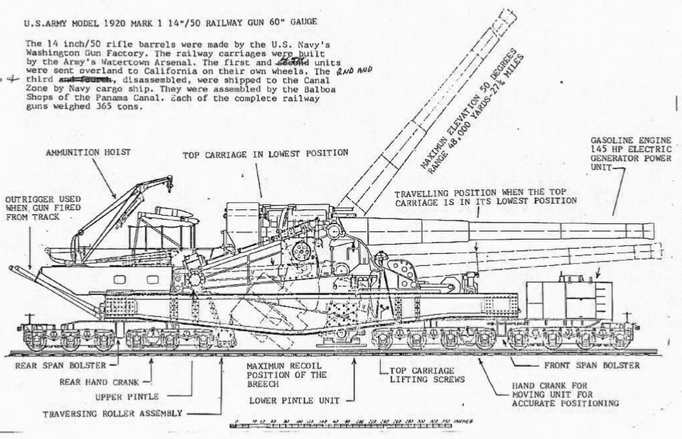
(U.S. Navy 14"/50 caliber M1920 railway gun on M1920 Carriage)
The United States Army deployed two 14-inch M1920 railway guns, a powerful weapon system, to the Panama Canal Zone. The 14-inch railway guns arrived in 1928, a rare example of enhancement of Canal defenses between the world wars. They had fixed firing points at Fort Randolph on the Atlantic side of the Canal, and at Fort Grant’s Culebra Point on the Pacific side, but could also be fired while mounted on its railcar platform while shifting between the two coastal fort positions. These had a greater range than the earlier 14-inch gun emplacements – it being double at 48,000 yards. This range was double that of older 14″ coast defense guns in Panama, which is exactly why the M1920 was deployed – to extend reach. In fact, the two 14″ railway guns in Panama could cover approaches far out to sea.
Deployment: Panama Canal Zone During World War II.
Origins of the M1920 14-inch Mk IV Gun
Watervliet Arsenal manufactured four 14″ guns for this project in the mid-1920s, using the Mark IV naval design as the basis. By 1925 the first units were ready for testing, and they entered service a few years later. Army records list them as Gun, 14-inch, M1920 with individual serial numbers.
The 14-inch M1920 railway gun was built around a U.S. Navy-designed 14-inch/50 caliber gun. In fact, the gun barrel itself was the Navy’s Mark IV 14″ naval rifle. Ballistically, the M1920 gun was the same 14″/50 (355.6 mm) firing the same 1,560 lb projectiles out to about 26–27 miles. These were high-velocity naval guns (50 calibers long, meaning the barrel length was 50 times its diameter) originally intended for battleships. Several spares were available by the end of World War I. In absolute terms, the barrel was about 60 ft long.
Rather than designing a completely new piece, the Army’s Ordnance Department adopted this Mark IV naval gun for coast artillery use, but re-designated it as the 14-inch Gun, Model of 1920 (M1920) when paired with the new carriage. In other words, the “M1920” designation refers to the Army’s adaptation of the Navy Mk IV gun for the 1920-era railway mount, not a different caliber or fundamentally new gun. Of the four M1920 Railway gun weapons ultimately completed, the second and third ones built were the only two allocated to the Panama Canal Zone.
It’s important to clarify the nomenclature: “Mk IV” was the Navy’s mark number for the gun barrel design, whereas “M1920” was the Army’s model/year designation for the gun once adapted. Technically, they refer to the same 14-inch gun, but in Army service the piece was simply called 14″ Gun M1920. In fact, Army supply catalogs list two Mk.IV railway gun models as:
Gun, 14-inch, M1920MI Mk. IV Model 1, on Railway Mount M1920: Early M1920MI barrels had the centerline of the breechblock mechanism canted 16 degrees counterclockwise to fit recoil band
Gun, 14-inch, M1920MII Mk. IV Model 2, on Railway Mount M1920: Later M1920MII barrels had the breech mechanism set straight in relation to axis of tube. The Railway Guns in the Panama Canal Zone were this later M1920II type.
The M1920 Railway Gun Carriage
The railway mount that carried the 14″ gun was officially the 14-inch Railway Carriage, Model of 1920 (often shortened to “M1920 carriage”). Therefore the entire railway gun could correctly be called the ‘14-inch M1920 Railway Gun on M1920 Carriage’ or even most correctly, the ‘14-inch M1920II Railway Gun on M1920 Carriage’. Yet it is most often referred to in military FM and TM manuals as a ‘14-inch M1920 Railway Gun’.
This was the last model of railway gun deployed by the U.S. Army, an upgrade of the U.S. Navy 14"/50 caliber railway gun. After the close of World War I, the US Army wanted to incorporate the lessons learned from other railway gun mounts and fulfill coastal artillery requirements for hitting a moving target. An effort to design a more universal mount for the Navy's Mk. IV 14"/50 caliber gun was undertaken.
The 14-inch M1920 railway gun was the last large caliber railway gun to be deployed by the U.S. Army. A total of 4 were built by Watervliet Arsenal and remained In service from 1925 to 1946. All four guns were cut up for scrap by 1947.
The carriage was formidable: it consisted of a heavy steel girder frame supported by an enormous 14-axle railroad chassis (8-wheel bogie trucks in front, 6-wheel bogie trucks in rear) to distribute the 365-ton weight of gun and mount on the rails. In 1928 the causeway railroad to Fort Grant had to be rebuilt to support the loading of these guns. Dimensions were accordingly huge: the length of the entire gun car was roughly 90 feet, or more if one includes the barrel overhang.
While on its Railroad Configuration (Mounted Mode), the barrel could be raised to an angle of 50°elevation. However, it could only be fired from an elevation angle: approximately 0° to 19° on its rail trucks without platforming This was the maximum safe firing angle while the gun was still mounted on its bogies and rails. Why limited? Firing at steeper angles risked structural damage to the carriage and railbed because of the recoil forces and vertical breech movement. Also, in this railway mode, the gun could only fire with limited traverse (±7°) rotation without resorting to using curved track for a greater pivot.
Jacking Mechanism
But the key feature of the M1920 carriage was its ability to transform the Railway gun into a fixed firing platform (Dismounted Mode). The M1920 carriage was designed to be raised off its bogies and lowered onto a fixed firing platform. Built into the carriage were jacks or pivot supports. At a prepared firing site (like those at Fort Randolph and Fort Grant), a circular concrete pivot or a steel pedestal was in place. The gun car would be positioned over this pivot, then the bogies (trucks) could be rolled out from under the carriage after jacking up the frame. Once the trucks were clear, the carriage was lowered, seating a heavy pivot pin on the mount into the socket on the platform. The front and rear of the carriage frame would rest on sturdy pedestal supports.
This process effectively turned the railway gun into a fixed gun battery in a matter of hours, but with the ability to later recover and move it. The fixed mounting not only allowed 360° rotation for aiming, it greatly increased stability that was critical for tracking moving ships
Traversing Gear
When dismounted onto the pivot (see following photo), the gun could be traversed by a rack and pinion or other gearing engaging a circular rail or racer on the platform as in the photo below. When on its trucks as in the above photos, limited traverse was achieved by a system that could shift the car slightly on a curved section of track or by slewing the trucks.
In Panama, the Army built firing turntables on pilings at the forts – essentially large circular mount foundations – to utilize the full traverse ability. When dismounted for firing, the gun could be elevated to a maximum of 50° when emplaced on its pivot (or about 45–50° according to firing tables), which enabled long-range plunging fire. The gun’s traverse (horizontal aiming) was not limited when dismounted and properly emplaced on a central pivot (essentially converting it into a fixed turret), where it had a full 360° traverse.
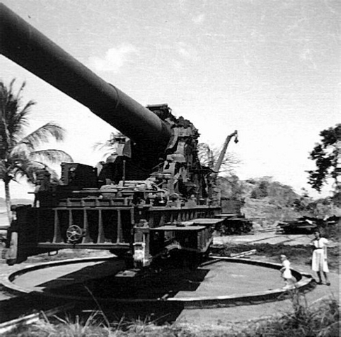
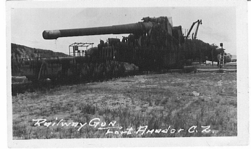
A dismounted and emplaced 14-inch M1920 railroad gun awaiting disposition after the war. This photo was taken at Fort Amador's Culebra Island. Noas Island can be seen in the background. This gun is waiting to be cut up like the barrels in the two above photos. All four guns were cut up for scrap in 1947.
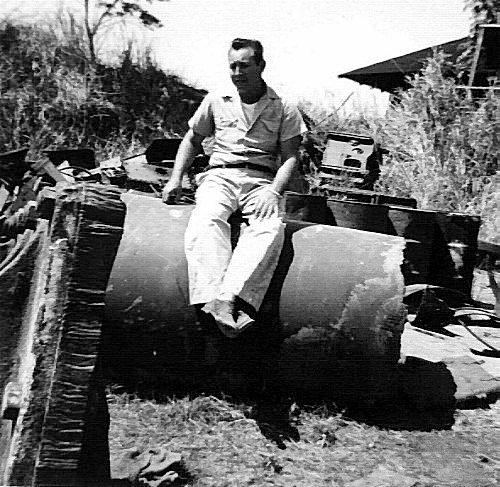
Above: Piece of barrel of the 14-inch railroad gun cut up.
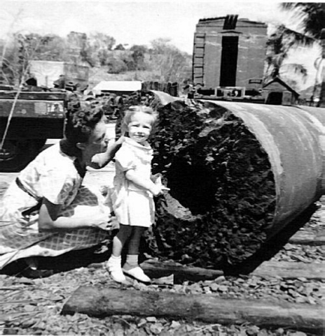
Above: Piece of barrel of the 14-inch railroad gun being cut up - Ammo Car in Background.
A dismounted and emplaced 14-inch M1920 railroad gun which could move from the Atlantic coast to the Pacific coast by railroad if needed.
There were two fixed gun emplacements for these 14-inch railroad guns at Fort Randolph (Atlantic Coast) and two more at Fort Amador (then Fort Grant on the Pacific Coast) at Culebra Island.
Typically, one gun would be dismounted and emplaced on each coast, and then moved to support the other gun if an enemy threat warranted the movement.
The Mk.IV gun was manufactured in two models:
Early model M1920MI with its centerline of breechblock mechanism canted 16 degrees counterclockwise to fit recoil band
Late model M1920MII breech mechanism is set straight in relation to axis of tube.
The rate of fire is one shot in three minutes for 14-inch railway mounts, and to one shot a minute for seacoast mounts, although upon occasions a more rapid rate of fire could be reached.
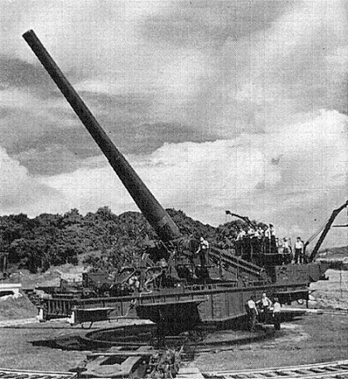
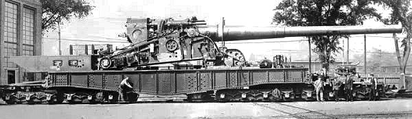
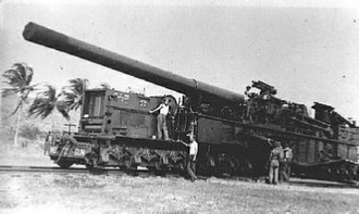
ABOVE: Notice the height of the gun over the railway bed is about twice the height of the man standing beside the gun to handle the raising and lowering controls. The bottom of the pivot wheel of the gun is about six feet above the railway chassis.
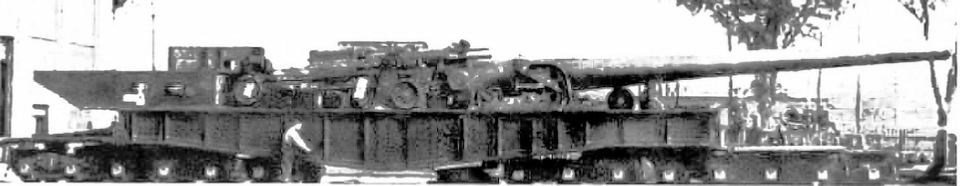
BELOW: The gun is lowered and secured by clamps, ready for railway movement. In this photo the gun over the railway bed is only about the same height as the man at the raising and lowering controls. The bottom of the pivot wheel is the same height as the railway chassis.
While the entire barrel could be raised to an angle of 50° degrees elevation, it could only be fired from 0° to 19° while on its railroad chassis. This practical limit prevented the recoil from over-stressing the rail supports.
The gun’s traverse (horizontal aiming) was similarly limited on rail: the carriage itself had a small built-in traverse of about 7° to either side on the rails. Traverse could be achieved by firing from slightly curved track segments, or pivoted using a traversing mechanism built into the trucks.
Crew Platforms
The sides of the carriage had retractable or fold-down platforms to give the gun crew footing. In travel, these would be folded in. In firing position, they’d be opened out, providing a working area around the breech for loading. The breech of the gun was an interrupted-screw type with step-cut threads, meaning a crew of a few men could open/close it, but handling the 1,400 lb projectiles required mechanical assistance. The carriage likely had a shell hoist or trolley. However, given that Panama’s firing positions had overhead shell-hoist cranes in their magazines, the on-carriage shell handling might have been minimal, relying instead on the infrastructure at the emplacements.
Gun Crew Composition
Each emplacement of one gun is manned by a gun section (39 enlisted men) consisting of a gun squad, an ammunition squad, a mechanic, and a power plant operator. In addition, each emplacement has a staff sergeant (electrician) responsible to the battery executive for all electrical apparatus, and one motorcyclist, orderly, and messenger for the officer in charge of the emplacement.
Gun Squad.- The gun squad (23 enlisted men) consists of the gun commander, gun pointer, elevation setter, chief of breech, three telephone operators, and 16 cannoneers numbered from 1 to 16, inclusive.
Ammunition squad.- The ammunition squad (14 enlisted men) consists of a chief of squad, and 13 cannoneers numbered 17 to 29, inclusive. This squad is divided by its chief into details for the service of powder and projectiles as discussed later.
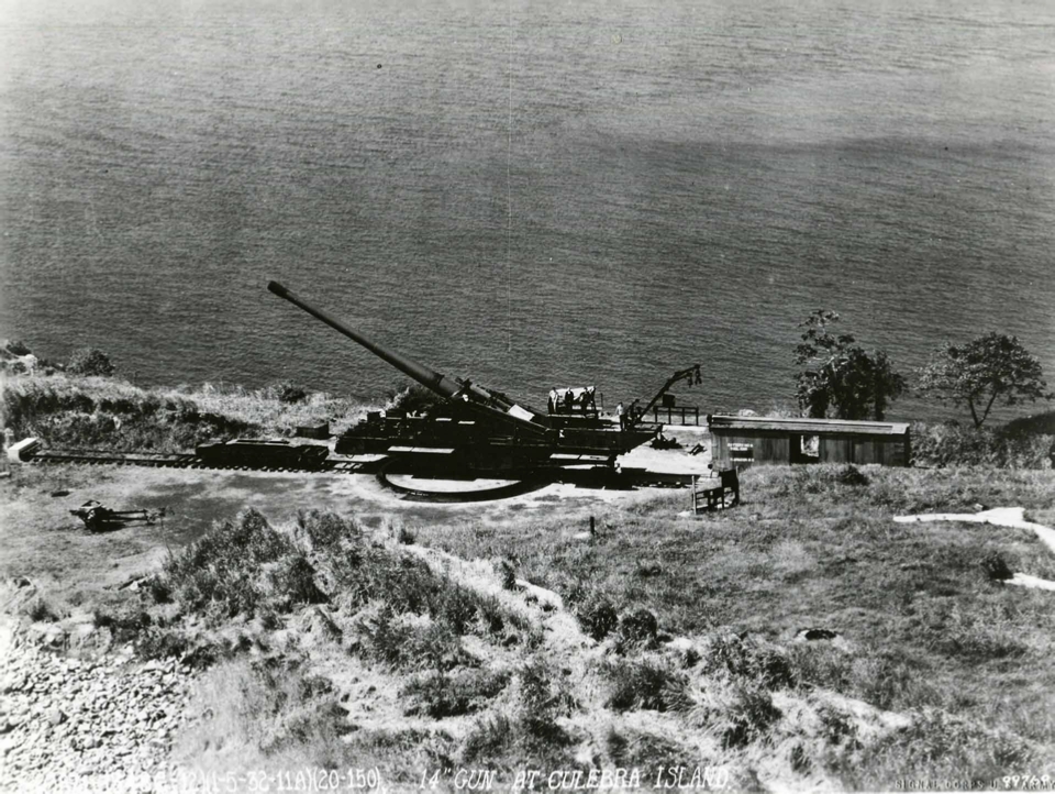
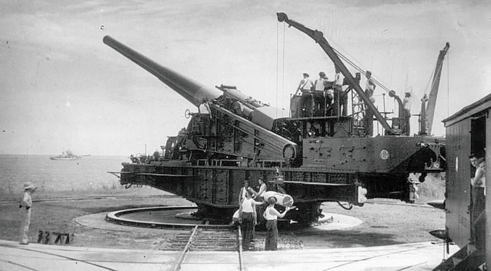
One of the two 14-inch two railway guns on Culebra Island in Panama is shown dismounted here in a 1932 photograph. The two guns on Culebra Island had a maximum range of 48,000 yards (twenty-seven miles). Notice the front and rear railroad bogies located just out from under the gun emplacement. Behind them, to the right, is an ammunition car to support the gun.
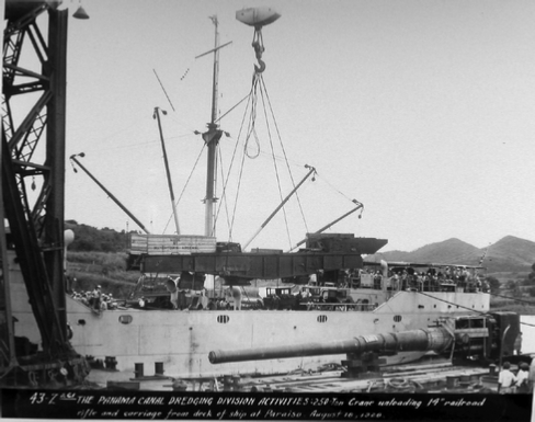
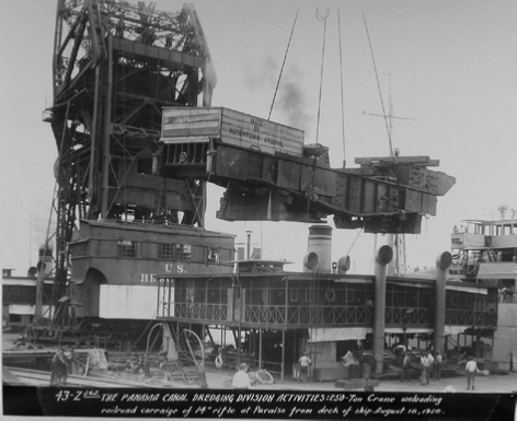
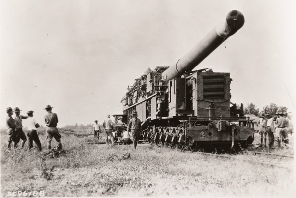
Unloading of 14" Rail Gun assembly at Paraiso in Panama on Aug.18,1928
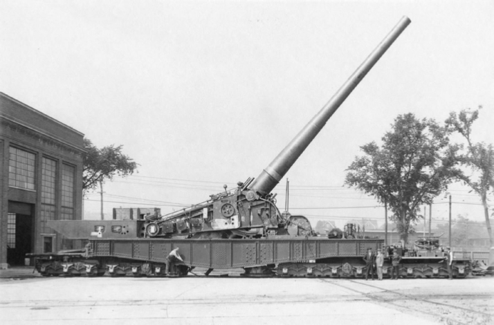
The primary difference from the earlier Navy versions lies in the M1920 carriage, which could be raised and lowered. (Below two photos). Additionally, prepositioned fixed mounts were installed at the forts, and the gun's rail trucks could be taken out from under the frame. (Third photo down).
After the removal of the rail trucks, the gun was lowered and bolted onto a pivot point for 360 degree movement. The M1920 carriage made the gun much more flexible. It allowed for the standard practice of using a curved piece of rail to traverse the gun, and it enabled the gun to be used in a fixed position. Two guns were deployed to. The two guns deployed to the Panama Canal Zone, a strategic waterway connecting the Atlantic and Pacific Oceans, could be moved to either coast on the Panama Canal Railway.
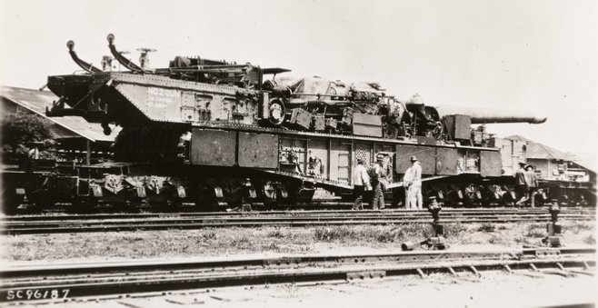
For transport, the gun sat on 6-axle and 8-axle trucks as seen in the above photos. The height was significant as well – In its lowered traveling position, the top of the transported gun stood nearly 20 feet off the rail. It could barely clear tunnels and bridges. In this transit position, the barrel could be depressed and secured down by clamps.
Functional Role in Panama
The gun car’s role was straightforward yet critical: it carried the big gun that could deliver 2,000 lb shells onto enemy targets at sea long before those targets could threaten the Canal. In the Canal Zone, two such railway guns were deployed – one generally assigned to the Pacific side (Fort Grant/Culebra Island) and one to the Atlantic side (Fort Randolph). They were considered a mobile reserve, able to reinforce either end as needed by crossing the isthmus on the railroad. Once at a fort spur, the gun car would be positioned onto its pre-surveyed firing point. At Fort Grant, for example, the firing point was on Culebra Island (one of the causeway islands offshore from Balboa) designated as “Battery No. 8” when the railway gun was in place. At Fort Randolph on the Atlantic side, a similar firing spur with a turntable was prepared.
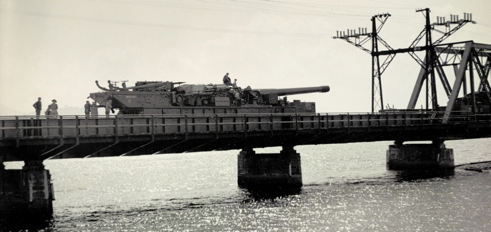
Right side and below - Railroad gun being prepared for rail movement across Panama on the Panama Railroad, May 1931 to the opposite fort battery.
In a typical operation: upon arrival, the train would push the gun car onto the spur until the carriage was exactly over the pivot platform.
The crew (which numbered around 200 personnel for the entire battery including support detachments) would then proceed to emplace the gun.
This involved hours of work: uncoupling the support cars and locomotive, aligning the carriage, using jacks to lift it, unbolting and rolling away the 7-axle bogies, then lowering the carriage frame onto the pivot pintle.
Once secured, the gun crew would connect communications lines (telephones to the fire control car or fort command post), set up the panoramic sights, and prepare ammunition from the accompanying cars or from the fort’s magazines. In Panama’s case, special “garage-like magazines with overhead trolleys” were built adjacent to the firing spur, so the heavy shells and powder could be stored safely and then moved by hoist directly to the gun’s breech area. This integration of the railway gun with fixed infrastructure was unique – it basically gave the best of both worlds: the gun could be mobile strategically, but when in firing position it had all the ammo handling benefits of a permanent battery.
When ordered to fire, the railway gun could be loaded essentially like a normal coast artillery piece. The projectile would be hoisted and rammed into the breech, followed by powder bags (the M1920 gun used separate-loading ammunition). Each shot required setting the elevation and azimuth. If the target was moving (e.g., a ship), the ability to rotate 360° on the pivot and to elevate/depress quickly was vital – this railway mount provided that flexibility. The fire control system supplied targeting data to the gun crew.
Top - Panama Canal Department. Department Maneuvers. Side view of 14'' R.R. Gun
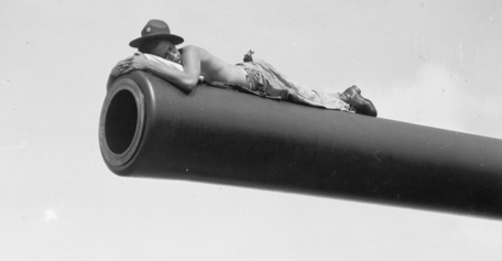
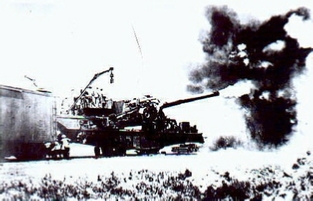
Side - Panama Canal Department. 'On the Alert' Time out for a snooze. Coast artilleryman catching a few short winks on the muzzle of a 14'' railway gun during the joint Army and Navy Maneuvers
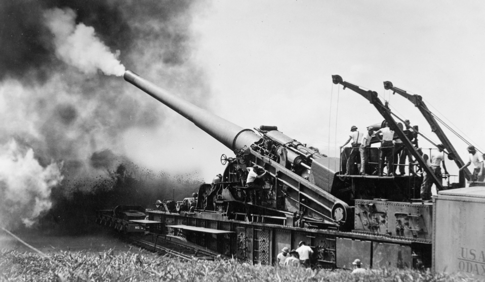
The firing itself was dramatic. Observers in the 1930s tests and later practice firings reported that the concussion could knock flatcars off rails from the shockwave if too close. During Panama trials, precautions were taken: support cars were positioned away under cover, and the gun was fired with a full complement of ear-splitting muzzle blast. The Army recorded that “the two guns on Culebra Island had a maximum range of 48,000 yards” and they conducted regular practice firings – one gun (No. 2) fired as many as 187 practice rounds during its service. The other (No. 1) fired 57 practice rounds. These drills ensured the crew could emplace and fire the weapon effectively. The last practice shots were fired on 8 December 1944, by which time the likelihood of a direct attack on Panama had waned.
Hydro-pneumatic Recoil System
The carriage included a built-in hydro-pneumatic recoil system – a set of hydraulic buffers and pneumatic recuperators that absorbed the gun’s recoil and returned it to battery after firing. This system was housed in a large recoil cylinder situated above the gun barrel (the “recoil band”). Despite this, firing such a gun still imparted massive forces. Each round fired was a separate-loading artillery round: a projectile weighing roughly 1,400–1,500 lbs for an AP Shell (armor-piercing shell), or slightly less for an HE Shell (high explosive shell), and a propelling charge of several hundred pounds of smokeless powder in silk bags placed behind the shell to fire it. The muzzle velocity was about 2,650 fps (808 m/s), giving a maximum range of about 48,000 yards (27 miles or 44 km).
This range was double that of older 14″ coast defense guns in Panama, which is exactly why the M1920 was deployed – to extend reach. In fact, the two 14″ railway guns in Panama could cover approaches far out to sea: they were positioned such that their fire sectors could overlap and reach well beyond the fixed batteries.
Gunlaying and Fire Control Features
The carriage had built-in ladders, sighting stations, and mounting points for instruments. For instance, a panoramic telescope (M1917 or M1922) could be mounted for direct aiming, and there were range scales and elevation indicators accessible to the gun crew on the carriage. The gun could be aimed in elevation via a large screw or hydraulic ram.
A small on-board electric generator (M1 generating unit) was mounted on the forward truck (Side Photo) to provide power for lighting and the operation of any electric gear.
Special Adaptations for Panama
The gun carriage cars sent to Panama were constructed to fit the broad gauge. This meant the trucks (bogies) were built wider than those for the pair of guns deployed in California (which ran on standard gauge). It’s likely that the bogies were a custom design or an adjustable design. There is a possibility that the carriages were built to standard gauge and then modified in Panama – but given the weight and strategic value, it’s more plausible that the two Panama units were manufactured or delivered with broad-gauge trucks. The tight clearances of the Panama Railroad also required adaptation. The Miraflores Tunnel, for instance, was just barely sufficient for the gun’s height and width. The 1934 article alludes to it being a “tight squeeze” through the tunnel.
To accommodate this, the gun needed to be lowered and strapped down. The Army may have even trimmed the tunnel lining or ensured nothing protruded. Also, track curvature in Panama was in spots relatively sharp (down to 9° curves). Operating in tropical conditions required attention to maintenance: the recoil system seals and hydraulic fluid had to be checked frequently because heat can thin the oil and humidity might cause condensation inside. The crew in Panama kept the gun and carriage heavily greased and painted to ward off rust from salt air.
One interesting note is camouflage and concealment – a form of adaptation to the environment. In the lush jungle and coastal terrain, the railway gun could be spotted by enemy reconnaissance if left in the open. Photographs from Fort Grant and Fort Randolph show that when not firing, the gun and carriage were often shrouded in camouflage nets or housed in a special shed. The Army built “long garage-like” concrete and steel sheds near the firing positions. These allowed the gun carriage to be rolled in under cover (concealing it from aerial observation and protecting it from the torrential tropical rains). When needed, the “garage” doors would open and the train would roll out to gather up the gun. This is an often-overlooked aspect of the Panama deployment: it was as much about fortification (with spurs, magazines, and shelters) as it was about mobility. The carriage itself wasn’t modified for this, but the usage was tailored to Panama’s static-yet-mobile concept.
Operational History and Procedures
In actual wartime service (1941–44), the railway gun in Panama never fired in anger at an enemy – no Axis warship ever approached Canal waters. However, it stood guard as a powerful deterrent. The operational routine was likely: maintain the gun in a ready-but-protected state at its home fort, train with practice drills, and if intel hinted at a threat to the opposite coast, prepare to rail-move the gun to the other side. Indeed, the guns were capable of shifting between coasts; however, during WWII each stayed on its respective side for the most part. The mere ability to rapidly reposition added a layer of defensive flexibility that enemy planners had to account for.
If a threat had emerged, say a Japanese task force approaching the Pacific entrance, the Army could have moved the Atlantic gun from Fort Randolph over to Fort Grant (Balboa) within a few hours, giving two guns to concentrate fire on one side. The Panama Railroad’s dispatchers were undoubtedly aware of this contingency, and the track was kept in top shape. (In fact, the railroad was upgraded and heavily maintained through the war, partially for this reason.)
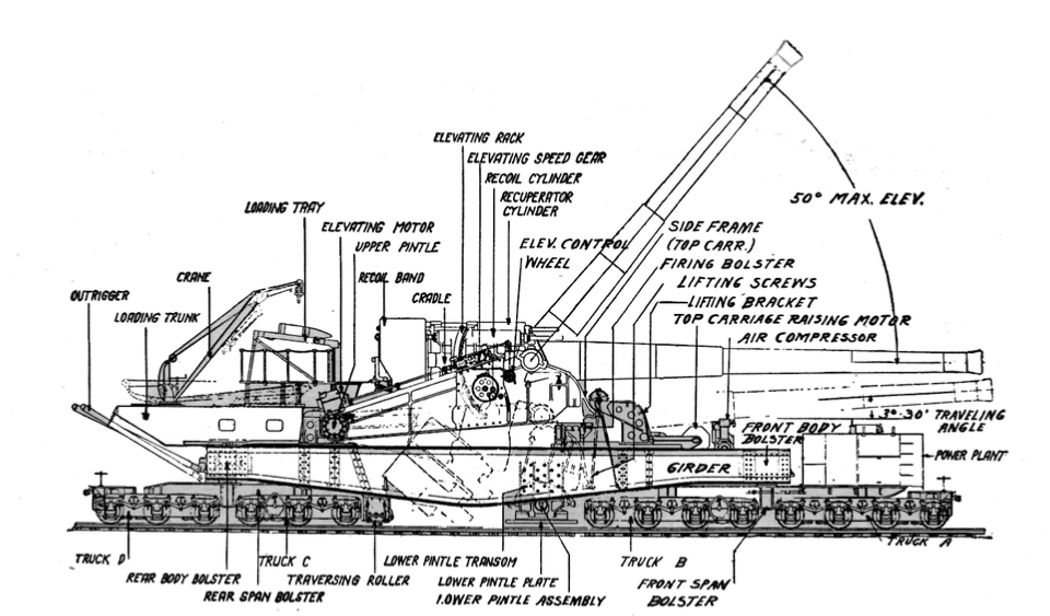
Good photos of the Panama railway guns are relatively rare but a 1932 photograph shows one of the guns on Culebra Island (Fort Grant) in firing position. In that image, the gun is on its pivot, with the long carriage frame visible and trucks removed. Another set of images from 1941 at Fort MacArthur (California) – which used identical equipment – shows the entire train: a camouflage net covers the gun (indistinct underneath), and five support cars stretch behind. One can make out the immense length of the carriage and the barrel sticking out under the net. Close-up drawings (like those in Popular Mechanics 1934) give perhaps the best detail: they show the profile of the gun car on rails and then an illustration of it emplaced on a pivot with full elevation. These drawings highlight features like the jacks, the pivot plate, and the general arrangement of the carriage.
The Legacy
The Gun Carriage Car with the M1920 14-inch railway gun was a mobile super-gun: technically sophisticated (with its retractable carriage), extraordinarily powerful in range and effect, and integrated into Panama’s coastal defense plan. Its presence allowed the Canal Zone to project firepower 27 miles out to sea from either entrance of the canal. While it never had to engage an enemy, the component itself performed exactly as intended in all tests and drills. It was the backbone of the railway battery – without it, the rest of the train had no purpose.
By 1944, the strategic situation had changed – the threat to Panama diminished – and these railway guns were put in “secondary status” (mothballed, essentially. Post-war, the Army had little use for them. In 1946 all four M1920 guns (the two in Panama and two in California) were ordered scrapped. In Panama, they were dismounted and cut up for scrap by 1947, an ignoble end for such titanic weapons. Today, no part of the gun carriage or barrel is known to survive; only concrete foundations and a few photographs and diagrams remain.
A final drawing detailing in dark gray all the parts involved in raising and lowering the gun on its mount, as well as showing the breech block position in a fully elevated barrel angle.