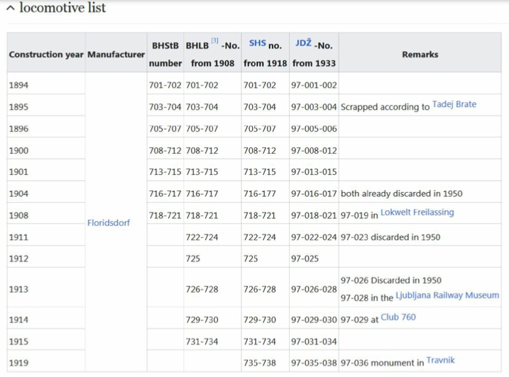
The series IIIc5 701–721 were three coupled axles for adhesion and rack and pinion traction in Bosnian gauge , procured by the Bosnian-Herzegovinian State Railways (BHStB). Their successors, the Bosnian-Herzegovinian State Railways (BHLB) and the Railways of the Kingdom of Serbia, Croatia and Slovenia (SHS), put another 17 units of the series into service. The Yugoslav Railways (JDŽ, later JŽ) designated the series as the 97 series. With 38 examples, it is the largest number of cog wheel locomotives in the world.
In 1891 the Bosnian-Herzegovinian State Railways (BHStB) put its first rack railway into operation , the Narenta Railway , which connected Sarajevo with Mostar and the Adriatic Sea via the Ivan Pass . Eight class IIIb4 locomotives with Klose support tenders , which transported a trailer load of 60 tons on a gradient of 60 ‰, took care of the train transport on the cogwheel line. Because the BHStB on the occasion of the commissioning of the route from Travnik over the Komar Pass to Donji VakufIn 1894, more cogwheel locomotives were needed, the IIIb4 were further developed into the more powerful IIIc5 series with an enlarged boiler and two-axle support tender. The wet steam locomotives were in turn supplied by the Viennese Lokomotivfabrik Floridsdorf , which owned the license for the Abt rack railway system for the territory of the then Austro-Hungarian Monarchy .
Technical Features
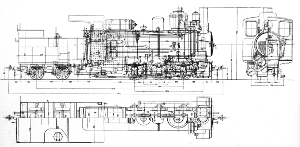
As a further development of the IIIb4 , the IIIc5 series is structurally very similar to its predecessor. The narrow Bosnian gauge made it necessary to use an outer frame for both types, in which the three coupled driving axles are mounted. As is usual with the cogwheel locomotives from the Floridsdorf locomotive factory , the cogwheel drive is designed as an internal drive unit within the locomotive frame. Both the external control for the adhesion drive and that for the gear drive were based on the Joy system.
Five independent braking systems are available for a safe descent:
- A mechanical brake acting on the second and third adhesion axis , which is tightened with a hand crank and spindle in the driver's cab.
- Band brakes acting on the gear axles , which are also operated from the driver's cab with a hand crank and spindle.
- The counter -pressure brake of the adhesion engine.
- The counter-pressure brake of the gear drive, which together with the counter-pressure brake of the adhesion drive serves as a non-wearing service brake.
- The vacuum brake acting on the support tender and the attached wagons.
The follow-up orders were placed without any significant changes. The gear frame was reinforced with taller bars . From the second delivery onwards, the grate area was reduced to 1.58 m² and the wheelbases were slightly reduced. From the third partial series, the amount of cooling water for the counter-pressure brakes was increased from 0.4 to 0.55 m³. The last delivery received Knorr type exhaust steam preheaters. Due to the changes, the weight changed. The empty weight of the first locomotives was 27.2 tons, and 29.09 tons for the last partial series. Some locomotives received the Holden blue oil firing system to improve the air conditions in the tunnels.
Operation:
The machines transported 80 to 90 tons of trailer load on the inclines of 60 ‰ and developed an output of 300 hp . Trains with a wagon weight of 240 tons were transported with one traction locomotive and two pusher locomotives . The older IIIb4 series locomotives were handed over to the rack railway over the Komar Pass.
In 1906, Floridsdorf delivered two Mallet locomotives of the IIIc5 751-752 with a tender and an operating weight of 60 tons on a trial basis. Because they didn't prove themselves, more locomotives from the IIIc5 series, road numbers 701–721, were delivered from 1911 to 1919.
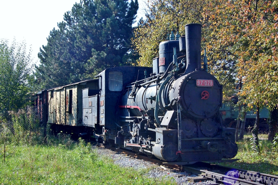
On the Yugoslav Railways (JDŽ, later JŽ), the support tender locomotives were given the numbers 97-001 to 97-038. They carried the brunt of the traffic on the two cog railways until the Sarajevo–Konjic line was gauge changed in 1966 and the cessation of operations over the Komar Pass in 1975.
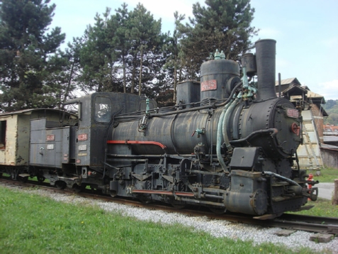
A few locomotives have survived. The following pictures illustrate the design of the IIIc5 701-721 series:
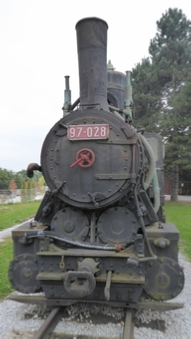
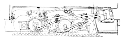
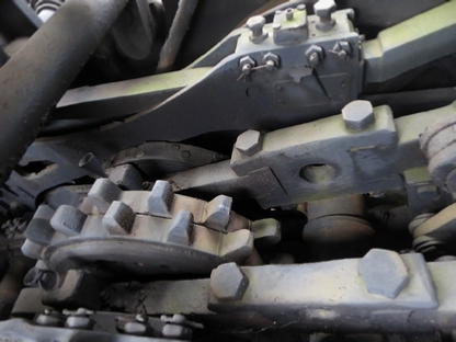
In the front view, above, the two outer cylinders for the adhesion drive with the slide boxes on top are clearly visible. The inner cylinders for the gear drive are located a little further up, their valve bodies are arranged at an angle. Below, notice the plan of the gear drive located within the locomotive frame. The two (inner) cylinders drive the two drive gears with simple steam expansion via two crossheads, connecting rods and Hall cranks.
Below: The single vapor expansion outer cylinders drive the third adhesion axis, which is connected to the first and second coupling axes by connecting rods and Hall cranks.
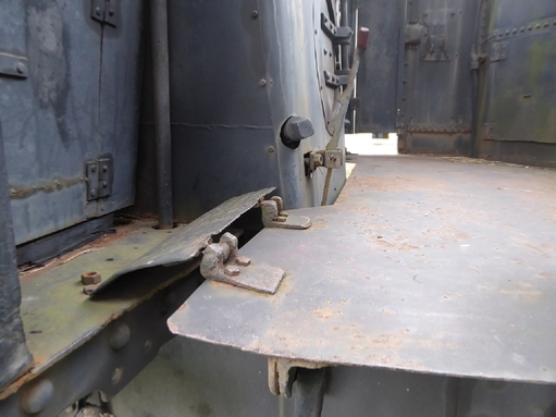
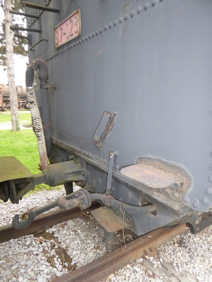
Below: Connection of the support tender with the horizontally rotatable crossbeam. In contrast to the predecessor type IIIb4, the cross member is arranged behind the standing boiler . The support tender can be separated from the locomotive by loosening the wedge.
The floor plates, some of which can be moved, allow the support tender to rotate, below.
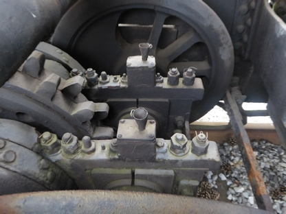
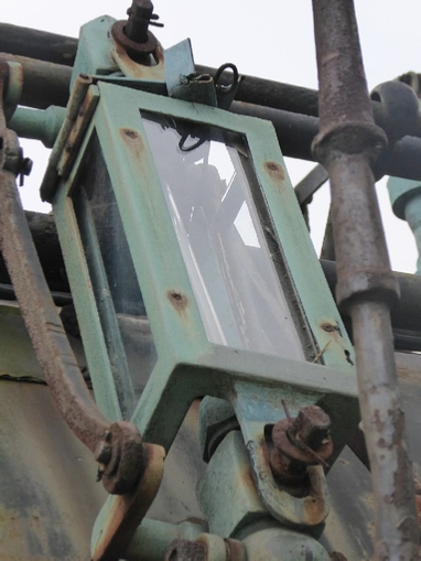
Below: The two sight glasses are attached directly to the long boiler because of the cramped space conditions in the driver 's cab . Their taps can be operated from the driver's cab.
Notice below one of the crossheads of the internal engine (in the background of the picture) drives the second non-visible pinion gear via a connecting rod . At the front of the picture are the two carriers for the drive gears and the other drive gear.
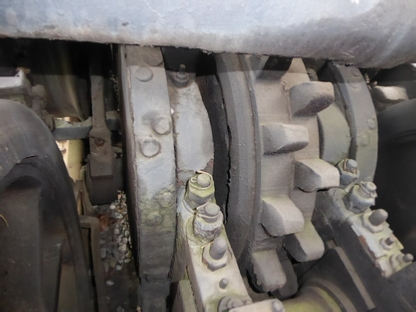
Below: Rear gear axle with control drive , left band brake , left carrier for the two drive gears, two-lamella drive gear system Abt , right carrier and right band brake.
Below: Mounting of the support frame for the drive gears on the rear coupled axle. The two funnels make it easier to oil the bearings .
Below: Front end of the support tender with connection for vacuum brake , central buffer coupling and steam heating line (from left to right)