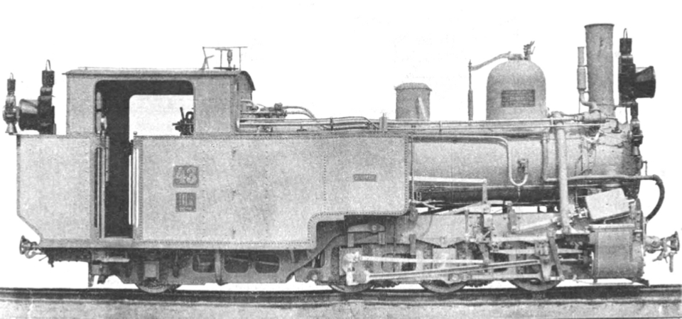
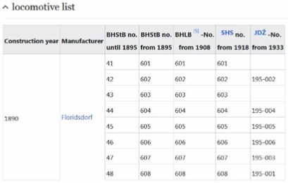
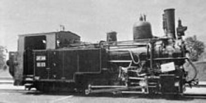
The IIIb4 series were Klose support tender locomotives with three coupled axles for adhesion and gear wheel drive in Bosnian gauge of the Bosnian-Herzegovinian State Railways (BHStB). On the Yugoslav Railways (JDŽ, later JŽ) they were designated as the 195 series.
The development of the country , which is criss- crossed by high mountains, deep gorges and dry areas, presented the Bosnian-Herzegovinian State Railway (BHStB) with obstacles that were difficult to overcome. The connection from Sarajevo over the Ivan Pass to the Adriatic Sea and later from Lašva through the Komar Pass to Jajce was realized with the help of rack railways.
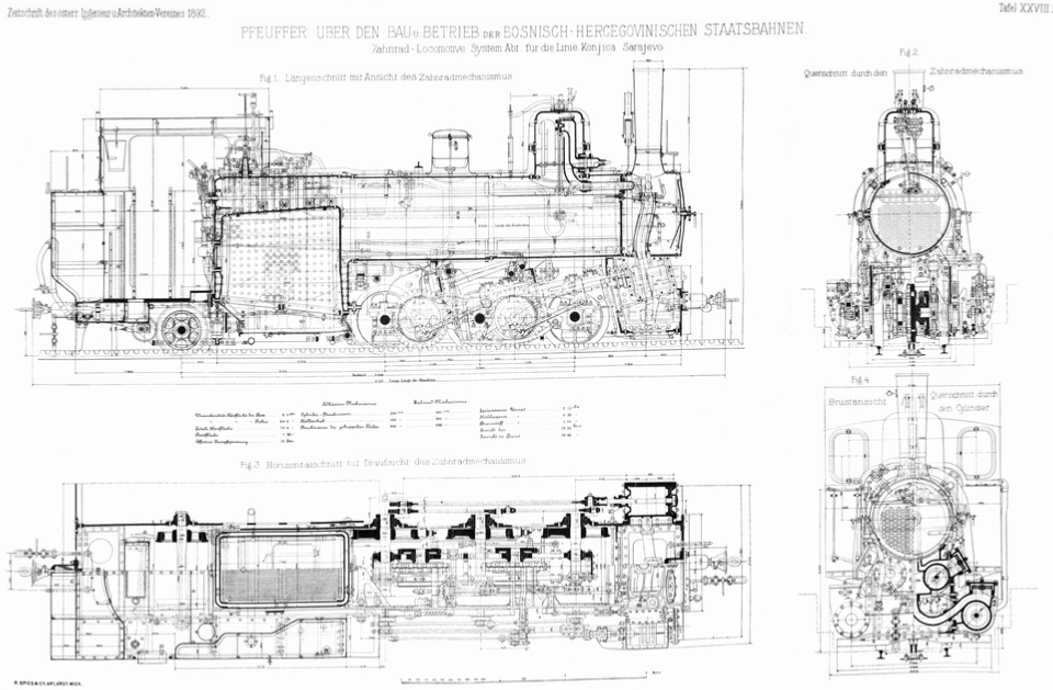
To haul trains on the Sarajevo – Konjic section of the Narenta Railway , which is equipped with rack and pinion, the BHStB procured eight wet -steam locomotives for mixed adhesion and rack and pinion system Abt from the Floridsdorf locomotive factory in Vienna . The specification called for a towed load of 110 tons on a gradient of 35 ‰ at a speed of 9 km/h on adhesion and rack and pinion routes. The construction of the machines took place with the participation of Roman Abts, the inventor of the rack and pinion system of the same name. The locomotives were handed over to the company in 1890. On August 1, 1891, the Sarajevo -Konjic section was opened.
Technical Features
Frame and Support Tender:
The difficulty in the construction of the IIIb4 series was the small space of only 690 mm width between the adhesion wheels to accommodate the gear drive caused by the narrow gauge of 76 cm . The three coupled driving axles were firmly mounted in the outer frame of the machine .
The water and coal boxes , driver's cab and coal box were set up on the moveable Klose support tender, with the water and fuel supplies being on either side of the standing boiler . The running axis of the Klose support tender could be adjusted radially and enabled good cornering mobility even in the smallest radii of 125 meters. The support tender was coupled to the locomotive frame in front of the standing boiler. The weight of the locomotive supported on the running axle was immediately behind the standing boiler with evolute springs transferred to the support tender. Wedge plates made it easier to return the support tender to the center position at the end of a curved track.
Adhesion and Gear Drive:
In addition to the adhesion drive , the machines were equipped with a completely separate drive for rack and pinion sections. On the rack sections, the two drives worked simultaneously. By supporting the adhesion drive, the load on the rack has been reduced. On adhesion routes, the gear drive was out of order.
The adhesion drive was provided by the cylinders arranged outside the frame with simple steam expansion to the third axle as the driving axle, which was connected to the first and second by means of Hall cranks and coupling rods . The external control of the adhesion drive was designed according to the Heusinger system .
The inner cylinders were screwed together within the locomotive frame and at the same time form the connection between the two frame sheets and the front support for the long boiler . The two inner cylinders drove the two two-piece drive gears, which meshed with the two -lamella Abt rack , via a crosshead , connecting rods and Hall cranks . The drive was located within the locomotive frame and was barely visible from the outside. The internal control of the gear drive was based on the Joy system due to the cramped space conditions executed. The movement was derived from the connecting rod of the rear gear wheel axle and transmitted outwards to the slides via an intermediate shaft. The slide boxes were arranged on the outside of the cylinders above the frame and, like the slide boxes of the adhesion drive, were easily accessible via removable cylinder covers.
The two gear axles between the first and second as well as between the second and third adhesion axle were arranged in a support frame, which in turn was mounted on the first and third drive axle. The suspension of the gear rack on the adhesion axles prevented the rack meshing from being affected by the spring movements of the locomotive frame. To also check the influence of wheel tires. To eliminate wear and tear on the meshing of the teeth, the gear axles could be adjusted by means of spacer plates in the supporting frame, so that the wheel tires could be brought back into the correct meshing as the wear progressed. The two ring gears of the drive gears were connected to each other by carrier springs in order to distribute the tooth pressure evenly to the two lamellae of the Abt rack even if the rack was inaccurate.
The engine driver controls the filling of the adhesion and gear cylinders by means of separate, independent reversing devices. There were also separate regulators with the corresponding hand levers in the driver's cab for the steam lines to the inner and outer pairs of cylinders. In the driver's cab, a colored disc driven by the slide rod of the internal control showed the speed of the driving gears to make it easier for the engine driver to enter the rack .
Brakes and Other Equipment:
The locomotives had five different braking systems :
- Mechanical brake acting on the second and third adhesion axis, which was tightened with a hand crank and spindle in the heater stand
- Band brakes acting on the gear axles , which were also operated from the driver's cab by means of a hand crank and spindle
- Counter-pressure brake for the adhesion cylinder
- Counter-pressure brake for the gear cylinders. The two counter-pressure brakes were used as wear-free service brakes on the descent.
- Vacuum brake system Hardy, which acted on the wheels of the attached wagons.
In addition, the machines were equipped with the facility for steam heating of the cars and a speedometer system Klose . The boiler is fed with suction injectors from the Friedmann system . Two sight glasses attached to the side of the round boiler were used to monitor the water level in the boiler , the taps of which were operated from the driver's cab. A Kernaul system lubrication pump, which can be operated from the driver's cab, supplied the pistons and slides with oil. When arranging the more than 50 handles on the driver's cab, the lateral movements of the support tender had to be taken into account. The gear drive controls featured a small bead.
Operation:
The locomotives transported a towed load of 60 tons at a speed of 8 to 8½ km/h on the up to 60 ‰ steep mountain route over the Ivan Pass . Trains with a load of up to 110 tons were either transported with an additional pusher locomotive or divided.
As the successor to the IIIb4 series, the IIIc5 series with a two-axle support tender was procured from 1894 to 1919. This significantly strengthened version of the IIIb4 is the most frequently built cogwheel locomotive in the world. The IIIb4 were now used on the 1895 opened Travnik - Donji Vakuf rack railway over the Komar Pass, which was less steep than the Narentabahn with 45 ‰ . In 1975, railway operations were discontinued by Komar. None of the eight Class IIIb4 locomotives have survived.